- 您现在的位置:买卖IC网 > Sheet目录240 > PAXLRT00 (Red Lion Controls)METER RTD TEMP 4-DIGIT
�� �
�
�5.0� C� ALIBRATING�
�CALIBRATION� MODE�
�THE�
�M� ETER�
�METER� INPUT� CALIBRATION�
�?�
�????� ?�
�??�
�?� to� ??�
�?�
�????� ?�
�??�
�To� enter� Calibration� Mode,� select� ???� <� >� ???� at� the� end�
�of� Programming� Mode,� and� press� the� PAR� key.� In� Calibration� Mode,� the� user�
�can� restore� the� meter� to� factory� default� settings� or� recalibrate� the� signal� input� if�
�necessary.�
�To� prevent� inadvertent� entries,� an� access� code� must� be� entered� to� perform� any�
�operation� in� Calibration� Mode.� Upon� entering� Calibration� Mode,� the� meter�
�initially� displays� Code� 50.� Press� the� up� or� down� arrow� keys� to� select� the� access�
�code� for� the� desired� operation.� If� an� access� code� other� than� those� shown� below�
�is� entered,� the� meter� exits� Calibration� Mode� and� returns� to� normal� display� mode.�
�The� meter� has� been� fully� calibrated� at� the� factory.� If� the� meter� appears� to� be�
�indicating� incorrectly� or� inaccurately,� refer� to� the� troubleshooting� section�
�before� attempting� this� procedure.� When� re-calibration� is� required� (generally�
�every� 2� years)� ,� the� procedure� should� only� be� performed� by� qualified�
�technicians� using� appropriate� equipment.� Resistance� source� accuracies� of�
�0.02%� or� better� are� required.�
�The� procedure� consists� of� applying� accurate� signal� levels� to� the� meter� input�
�in� a� series� of� two� steps.� Allow� a� 30-minute� warm-up� period� before� starting�
�calibration.� To� begin� the� input� calibration,� enter� access� Code� 48� and� press� the�
�PAR� key� .�
�?�
�????� ?�
�??�
�FACTORY� SETTINGS�
�ENTER� ZERO� REFERENCE�
�Meter� displays� ??� .� Apply� 0� ohms� to� the� meter� input� by� shorting� Terminals� 4,�
�5,� and� 6.� Allow� the� meter� to� stabilize� at� least� 20� seconds� after� shorting� the�
�terminals,� and� then� press� PAR� .�
�The� factory� settings� for� the� programming� parameters� are� shown� in� the�
�previous� section� in� the� alternating� display� illustrations.� All� programming�
�parameters� can� be� restored� to� the� factory� default� settings� by� entering� the� access�
�Code� 66� and� pressing� the� PAR� key.� The� meter� briefly� displays� ????� and� then�
�returns� to� Code� 50.� This� procedure� resets� only� parameters� that� are� accessed�
�through� Programming� Mode.� The� Calibration� Mode� settings� (input� calibration�
�levels)� are� not� affected.�
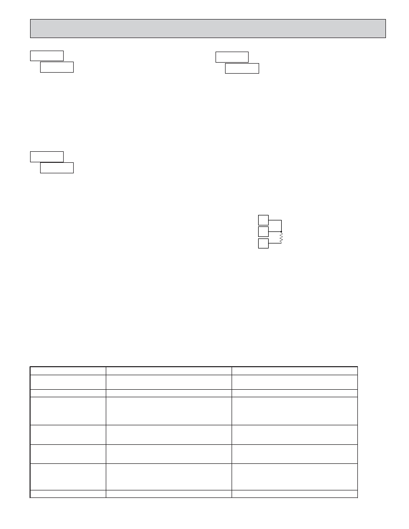
�APPLY� PRECISION� RESISTANCE�
�Meter� displays� ????� .� Connect� a� precision� 300� ohm� resistor� across� Terminals�
�5� and� 6.� Terminals� 4� and� 5� remain� shorted.� (Note:� Be� certain� to� short� Terminals�
�4� and� 5� at� the� resistor� as� shown� in� the� drawing� below.� Shorting� terminals� may�
�lead� to� incorrect� calibration.)�
�4�
�5�
�6�
�Allow� the� meter� to� stabilize� at� least� 20� seconds� after� making� the� connections,�
�and� then� press� PAR� .� The� meter� briefly� displays� ???� and� returns� to� the� normal�
�display� mode.� Calibration� is� now� complete.� It� is� recommended� to� check�
�calibration� by� comparing� the� displayed� temperature� with� a� precision� thermometer.�
�TROUBLESHOOTING�
�The� majority� of� all� problems� with� the� meter� can� be� traced� to� improper� connections� or� improper� programming� set-ups.� Be� sure� all� connections� are�
�clean� and� tight� and� check� the� programming� set-ups� for� correct� data.�
�For� further� technical� assistance,� contact� technical� support� at� the� appropriate� company� numbers� listed.�
�PROBLEM�
�NO� DISPLAY�
�“� ????� ”� IN� DISPLAY�
�“� ??� ??� ??� ?� ”� or� “� ???� ??� ??� ?� ”� IN� DISPLAY�
�DISPLAY� WANDERS�
�JITTERY� DISPLAY�
�POSSIBLE� CAUSE�
�1.� Power� off,� improperly� connected,� or� brown-out.�
�1.� Program� data� error.�
�1.� Input� display� out� of� range.�
�2.� Loss� of� data� set-ups.�
�1.� Loss� of� data� set-ups.�
�1.� Electrical� “Noise”� in� process� or� sensor� lines.�
�2.� Process� inherently� unstable.�
�REMEDIES�
�1a.� Check� wiring.�
�1b.� Verify� power.�
�1.� Press� PAR� and� check� data� set-ups.�
�1a.� Change� display� resolution� to� “1”� degree.�
�1b.� Reduce� offset� value.�
�2a.� Check� data� set-ups.�
�2b.� Check� for� electrical� disturbance.�
�2c.� Disconnect� and� reconnect� power.�
�1a.� Check� data� set-ups.�
�1b.� Disconnect� and� reconnect� power.�
�1c.� Check� for� electrical� disturbance.�
�1a.� Increase� digital� filtering.�
�1b.� Re-route� signal� wires.�
�2.� Dampen� process� to� eliminate� oscillations.�
�“� ????� ”� IN� DISPLAY�
�1.�
�2.�
�3.�
�4.�
�Probe� unconnencted.�
�Broken� or� burnout� probe.�
�Excessive� probe� temperature.�
�Input� overload.�
�1.�
�2.�
�3.�
�4.�
�Connect� probe.�
�Repair� or� obtain� new� probe.�
�Reduce� temperature.�
�Check� input� levels.�
�“� ????� ”� IN� DISPLAY�
�1.� Input� shorted.�
�7�
�1.� Check� input� connections.�
�发布紧急采购,3分钟左右您将得到回复。
相关PDF资料
PAXLSG00
METER STRAIN GAGE 3 1/2-DIGIT
PAXLTC00
METER THERMOCOUPLE 4-DIGIT
PAXLVA00
VOLTMETER AC 3 1/2-DIGIT
PAXLVD00
VOLTMETER DC 3 1/2-DIGIT
PAXTM100
TIMER DISPLAY 1/8 DIN PRESET 6 D
PB-1583-TF
BOX ABS 4.37X3.12X2" BK 1=10PCS
PB-1583
BOX ABS 4.37X3.12X2" BK 1=10PCS
PBS-11273
BOX ABS 6.30" X 3.75" X 1.41" BK
相关代理商/技术参数
PAXLSG00
功能描述:METER STRAIN GAGE 3 1/2-DIGIT RoHS:否 类别:工业控制,仪表 >> 仪表 - 面板,数字 系列:PAX®LITE 标准包装:12 系列:* 其它名称:Q7072030
PAXLT000
制造商:Red Lion Controls 功能描述:METER, TC/RTD TEMP WITH DUAL RELAY 制造商:Red Lion Controls 功能描述:TC/RTD TEMP WITH DUAL RELAY
PAXLT0U0
制造商:Red Lion Controls 功能描述:METER, UL LISTED TC/RTD TEMP W/ D RELAY 制造商:Red Lion Controls 功能描述:UL LISTED TC/RTD TEMP WITH DUAL
PAXLTC00
功能描述:METER THERMOCOUPLE 4-DIGIT RoHS:否 类别:工业控制,仪表 >> 仪表 - 面板,数字 系列:PAX®LITE 标准包装:12 系列:* 其它名称:Q7072030
PAXLVA00
功能描述:VOLTMETER AC 3 1/2-DIGIT RoHS:是 类别:工业控制,仪表 >> 仪表 - 面板,数字 系列:PAX®LITE 标准包装:12 系列:* 其它名称:Q7072030
PAXLVD00
功能描述:VOLTMETER DC 3 1/2-DIGIT RoHS:是 类别:工业控制,仪表 >> 仪表 - 面板,数字 系列:PAX®LITE 标准包装:12 系列:* 其它名称:Q7072030
PAXOEMS1
制造商:Red Lion Controls 功能描述:SOFTWARE AND USB CABLE RS232
PAXOEMSS
制造商:Red Lion Controls 功能描述:SOFTWARE AND CABLE RS232 制造商:Red Lion Controls 功能描述:SOFTWARE AND CABLE, RS232 制造商:Red Lion Controls 功能描述:SOFTWARE AND CABLE, RS232; For Use With:PAXI Counter Display; SVHC:No SVHC (19-Dec-2012) ;RoHS Compliant: Yes